
Our field of expertise
Hoisting frames for Fehmarnbelt
Precision in motion
Saltwater is contributing to the Fehmarnbelt Tunnel, which will be the world’s longest immersed tunnel at 18 km. Connecting Denmark and Germany by road and rail, it is set to open in 2029 and will greatly enhance Europe’s cross-border infrastructure.
Within the scope of Saltwater’s work on the maintenance barge, commissioned by FLC, one area where mechanical expertise played a key role was the detailed engineering of the hoisting frames.
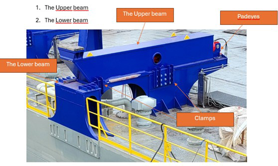
The hoisting frames, as shown in Figure 1*, consist of two main components:
1. The upper beam
2. The lower beam
These two parts are connected by a hydraulic cylinder, which allows the upper beam to move back and forth along the lower beam.
Due to the complex structure and the large number of assemblies within the hoisting frames, all welds and machining operations were first modeled in Autodesk Inventor before the detailed engineering phase could begin. This preliminary step ensured that the hoisting frames could be produced according to the required specifications.
While modeling the welds, it was discovered that the attachment points (padeyes) of the hydraulic cylinder in the upper beam were positioned too close together. This made it difficult for the welder to apply the specified weld thickness and type. In consultation with the client, it was ultimately decided to use a bolted connection to mount the padeyes in the upper beam instead.
As mentioned earlier, the upper beam moves back and forth with a hydraulic cylinder to enable linear movement. This cylinder was selected using a configurator from Vremac. By inputting parameters such as bore and rod diameter, required stroke length, and cylinder mounting type, the configurator calculated the installation dimension (eye-to-eye distance), which was then used to ensure a proper fit between the upper and lower beam.
Engineering for a perfect fit
During the detailed engineering phase, several types of tolerances and fits were considered:
- Concentricity tolerance
Applied to the facing padeye holes and the bolted joints of the clamps, to ensure proper alignment between bolts and holes.
- Straightness tolerance
Applied to the bottom plate of the upper beam and the pins of the cylinder. This ensures that the plate is not warped, allowing the upper beam to slide freely, and that the pins fit accurately between the padeyes and cylinder eyes.
- Squareness tolerance
Applied to the padeyes to ensure that they remain correctly aligned so the cylinder pins fit properly.
- Flatness tolerance of the top plate of the lower beam
Ensures that the surface is sufficiently flat so that the upper beam can move smoothly across it.
- Loose fit
Refers to the fit between the cylinder pin diameter and the padeye holes. This fit was calculated with tolerances in mind to ensure the cylinder can align and move freely.
Since all welding operations were already modeled in Inventor, it was possible to efficiently generate detailed drawings for all components. These included milling, turning, and cutting operations, forming a comprehensive basis for fabrication.
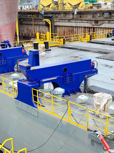
Credit: Helen, 2025
The Fehmarnbelt Project

Specific project data
Project information
Scope of work:
- 3D modelling of the welds and pre-processing of the hoisting frames
- Selection and integration of the hydraulic cylinder
- 2D production drawing with required welds, fits and tolerances
- 2D production drawings of all parts to be pre-machined
Deliverables:
- Hydraulic cylinder selection
- 2D production drawings: Detailed construction plan